Networking Sections

Router Down

In this task, a site's network is offline due to its router being offline. This is a retail site so the router being down only allows them to do cash sales. This will affect the business heavily and their potential sales and profits. The router is a layer 3 part and handles the routing of data inside the network and the data coming in and out of the network, it sends the data outside of the network via the default gateway. Due to the router being offline, data cannot leave the network and if it is fully offline, data cannot be moved locally or within the LAN. For example, the layer 2 switches won't be able to communicate with each other, leading to tills, PCs, tablets and more being offline too.


My task involves identifying the cause or causes of the router being down, troubleshooting it and finally bringing it back online making the store able to trade once again. The task may sound simple and be able to be typed in one sentence, but the process requires more steps.


When a router goes offline it will be alerted to us via our monitoring system called Pandora. For a router, it needs to be offline for 20 minutes before it alerts us, this changes based on what it is, for example, a lease line or head office going offline is alerted after 2 minutes and 4G routers are 60 minutes. When a router has been down for 20 minutes it sends an email alert to our Outlook inbox when then automatically raises the email as a ticket to our ticketing system, Autotask. An example of our ticket is below. This ticket reference for this case was T20230829.0202.
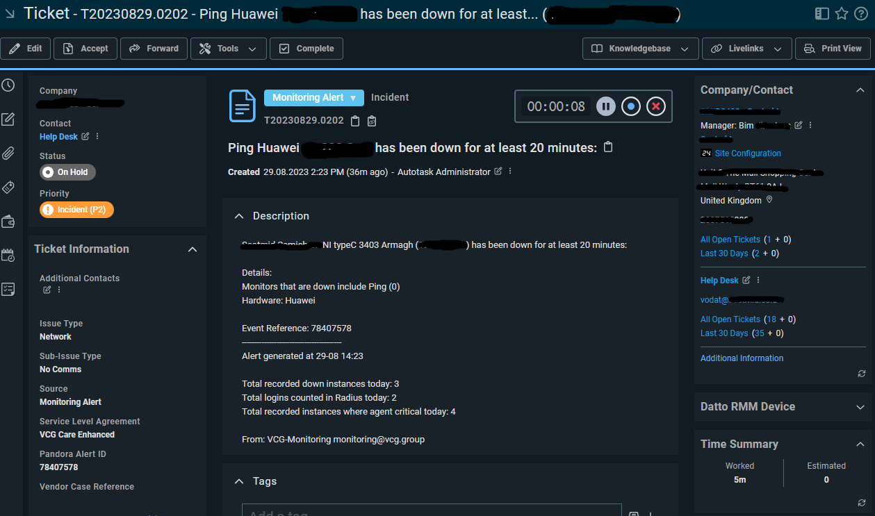
ticket

The official SLA for response time to a ticket like this is 1 hour and 8 hours for a resolution if it doesn’t need external teams, like Openreach or an engineer visit. These SLAs are important as it helps the customer understand the time we need to complete something and when it’s expected to be back up.

The next step is to ping the router as it could have come online since the ticket was raised or something else could have brought it back up and online. I use the PING command with the switch -t which makes the ping continuous. The ICMP packet will confirm whether the router is down.

ping

The continuous ping above shows that it has not been able to contact the router and has lost 100% of the packets it sent, meaning the router is still offline.

The next step is to run a line test. A line test is testing both the PSTN(if using one) and ADSL/FTTC/FTTP line all the way to the site from the provider. The reason we test the lines is that if either of the lines are having issues, this can impact the site down the line. If the line had a fault that could be the probable reason to why the router is down. For testing the PSTN we go through a portal called Abillity.

First, we log in to Abillity, then we select WLR3 Tools. The you put the CLI into he box and confirm the postcode. You are then able to run a test.
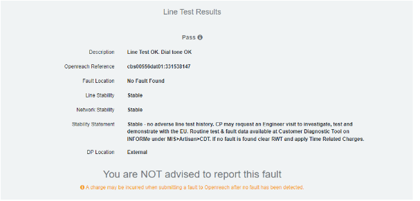
lines result

In this case, the test passed, so we moved on to testing the ADSL part of the line. If this failed and had a fault we would raise this to Openreach and if the site pays for a 4G drop-in service, provide a temporary router. To test the DSL part of the line, this site uses TTB as the provider and can be completed by doing the following.

sync

First, we log in and go to supportal, when we are there, we put in the CLI. We can then check if the line is in sync or not. In this case the line isn’t in sync so you will have to run a line test, but if it is in sync, then we can do a port reset. A port reset drops the port in the exchange and forces the router to reauthenticate, this can solve some issues with the router as if it is in sync but not authenticating you will get no internet. Since the line isn’t in sync we move to the next step.

Next, we select the service LLU and put in the CLI, this will populate the information about the line and allow you to run a line test, called a TAM test here. LLU stands for Local loop unbundling, and this allows for companies other than BT to give out broadband using Openreach lines. This means that TTB is using ORs lines to provide broadband to us.

llu

So, then we select TAM test and issue and it will show the result once complete. Once ran, it will show a result like below.

result

Since both line tests passed this means that the fault isn’t with the line but with the equipment on site. To test on-site equipment there are many steps, but we always do initial checks first as there isn’t much point in sending an engineer when we can bring the router back online over the phone if it is switched off for example. So, we do the initial checks over the phone to save time and make the work more efficient. When we call the site, we will check the lights that are at the front of the device as this will give us an indicator of what is going on here, for example, this site Had the PWR, SYS and VDSL lights on, but we also expect the PPP light on (Point to point protocol). Due to the PPP light not being on this will indicate an issue with the DSL cable as we send PPP over the line, but it’s getting a signal from the line as the VDSL light is on. So first we unplug the RJ11 cable from the router and plug it back in, when then do the same for the side that is connected to the filter into the master socket on the wall. This is due to over time it can get loose or tugged on and come loose. Usually, this can bring it back online and we run a continuous ping anyway just to see if it helps but it’s good practice to reboot the kit too as it gets a fresh connection and startup. We ask the site to unplug the power, wait 10-15 seconds then plug it back in. After this, we monitor the site to make sure comms return and the site is back online. In this case, the site starts to get successful pings as it comes back online showing that the router is getting a connection and is online. Shown below is the successful ping response.

test

I sent 47 ICMP packets and it was 100% successful. The reason we send so many is to make sure that the site is successfully stable. If the site had been down for an extended period, we may continue to monitor for a period of time to make sure nothing goes wrong with the site as it has been down for a while, when closing we would write something similar to the below.

intermittent

When closing the case we need to give proof it has been stable. The above photo shows our radius logs. This is a tool we use where we have a file with all the logins for the sites for PPP authentication. Every time a router authenticates it uses the logins from the USERS file on the radius server and connects to the internet using the PPP details stored. Every time a site successfully authenticates with the line and USERS file makes a log which is then stored on the radius. This allows us to see how many times a router authenticates with us allowing us to check if the connection is stable, if it is authenticating a lot then it shows that the connection isn’t stable. And it would need to be looked at. As you can see in the red circle it hasn’t needed to authenticate for the last week which means it has held that same connection without issue. The other piece of proof we provide is a standard ping response to show it’s currently online. If it has been down for a short period of time then we would use a closing message like below.

standard

This is obviously less detailed in showing that it has been stable as it isn’t referencing the radius logs, but it does explain what we did to bring it back online and shows a ping response as proof that it is online and currently online. Doing an in-depth stability check isn’t always required if the network went down briefly and was stable before as it could be as simple as it being accidentally unplugged. We still explain what we did to bring it online, but we don’t explain that we are going to monitor it as it isn’t required. This keeps the network security at a high level as the firmware versions we use are tested and have minimal flaws. The newest version is usually good but can have unforeseen bugs and flaws so it's important to use a version with a good knowledge base behind it. Overall, this was resolved in the first response which was 35 mins after the ticket was raised. This fulfils both the first response SLA of 1 hour and resolution SLA of 8 Hours.
VLAN Configuration

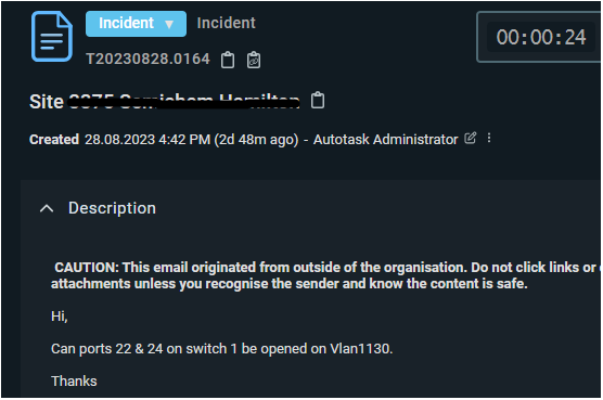
For this task I had to add Vlan 1130 to two ports which were shutdown and only had a certain LAN range that didn't include Vlan 1130. Below is the ticket we received.

ticket

A VLAN is a virtual local area network which is its own partitioned bit of the network at the data layer of the OSI model. Virtual in this sense means that it has been altered by the extra logic required for a VLAN to work. They work by applying a tag to make it function and appear as a single network but acts as if they are separate networks. It's fundamentally different to something like a subnet as it works on MAC addresses which is on layer 2 and subnets work on IP addresses which is on layer 3. It also has different amounts of use cases as VLANs can create different physical and logical addresses, on the other hand Subnets can only create logical networks within the same physical network.

After having a look at the switch, I found that ports 20 - 24 were shutdown and only allowed ranges 1 - 1005 by using the command sh interface status. My tasks were I had to bring the ports back online and allow the access through the new VLAN 1130.

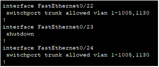
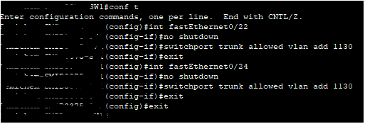
First I used the command conf t to get into the config, I then used int fastEthernet 0/22 to get to port 22. I then did shutdown, to bring it back online and switchport trunk allowed vlan add 1130 to add vlan 1130 to the allowed list over trunk. I then did the same for port 24

config

I then had to check the config by typing sh run to make sure the settings had applied. below shows that ports 22 and 24 are online and allowing vlan1130.

config

We then showed the screenshots of it working and the switch passing vlan1130, which allowed us to close the case. Overall, this job took 30 minutes for the first response and resolution which is within the 1-hour response and 8-hour resolution time.

Port Forwarding

This task a new site has installed 2 switches, and we will need to access them remotely for future configuration and troubleshooting. I was not at the site for this, but I was able to remotely access the router for the configuration of the port forwarding.
Port forwarding is part of Network Address Translation (NAT) that redirects requests from an IP and port to another while the packets are in transit. The is most commonly used to make services on a host which is in a private network available for external users.

Typical applications include the following:

•Running a public HTTP server within a private LAN

•Permitting Secure Shell access to a host on the private LAN from the Internet

•Permitting FTP access to a host on a private LAN from the Internet

•Running a publicly available game server within a private LAN

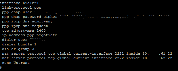
So first is had to enter sys mode which is similar to conf t on Cisco router but also some commands are hidden behind it like ssh etc. Once I am in system view, I must enter the dialler interface which I connected to the line and has the public ip assigned to it. I then type in this command:

nat server protocol tcp global current-interface 2221 inside ip-address 22

commands

nat server protocol tcp global is that it's using a nat command with the protocol of tcp and that its global. current-interface is that it uses the current interface which is dialler1 2221 is the external port, we then give the private IP address then the internal port which is 22. You For the second switch we change the external port to 2222 and the ip address, below is the config for dialler1, circled is the new commands for port forwarding the switches.

config

Once you have ensured it is in the config you need to save it which is a simple as typing save which is shown below:

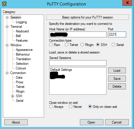
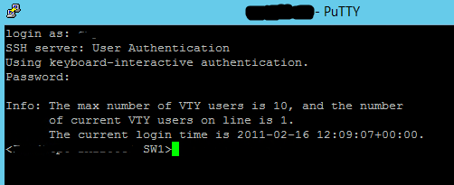
After we have saved the config we need to make sure that the port forward is working now so what we can do is put the IP into putty with the port that it is allocated to which for switch 1 was 2221:

This task was completed in 35 mins so the response and completion SLA was hit for this. I learnt about port forwarding on routers and how useful they can make troubleshooting for devices that we support that aren't directly connected to the router. I would of liked to do this with routers by manufacturers other than Huawei as it would show me how commands are different and it will help me develop this in the future.

Router Installation

One of the sites that we managed needed a new router as the current one was losing packets and sync. This was causing an issue with trade which means that it needs a replacement router installed and when we replace a router, we also replace the DSL cable and filter during this time if required. I was tasked with swapping the router and bringing the site back online to a stable connection.

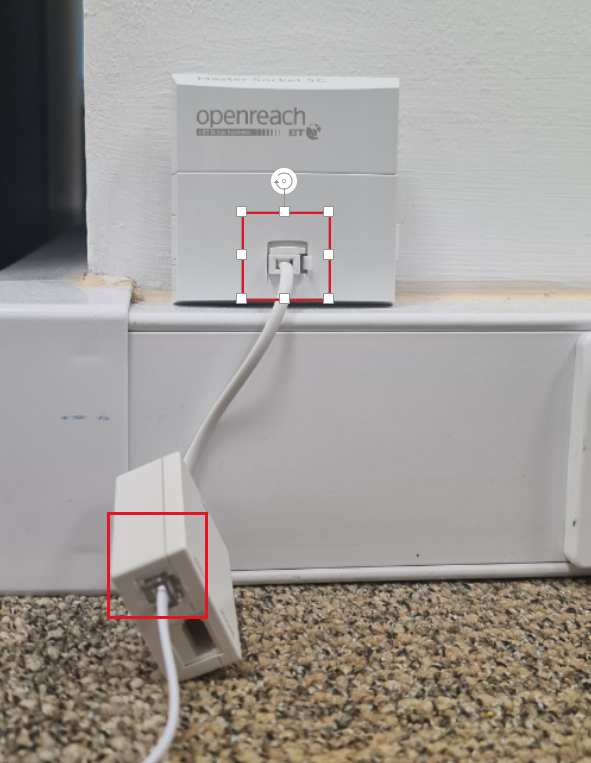
The first thing we need to do here is to install the new router and make sure it gains sync with the line. The old device was also a one access but faulty which increases the chances of it working on this line. The line we are installing this on is a DSL line which stands for digital subscriber line, the line was installed by Openreach which is standard for most homes but not guaranteed. We plug the filter into the socket on the wall and the DSL cable into the RJ11 connector in the filter that is for the modem and the RJ11 connector on the router. Usually, the sockets are labeled with the number of the line so if there were 2 you would know which one is which. Unfortunately, this one wasn't labeled, but there is only one line on-site with one termination, so this is highly likely to be the correct line. If there were 2 unlabelled sockets you can plug a phone into the socket and dial out with the phone to see the number. There are other lines that use a DSL terminal like FTTC which is fibre to the cabinet, that then uses copper to the property.

cabling

When I plugged in the power cable, I had to wait for the router to boot up and be able to gain sync. For this, I would need the status and IP light on the router. Eventually the router did have the correct lights on which means I can plug in a laptop into the router to check data passthrough. This router by default has no 802.11 trunk ports, so data can go through any of the RJ45 ethernet ports, but since some config is required, I am going to plug in my laptop to the console port on the router and this adapts from RJ45 to USB for it to connect to the laptop. Plugging into the console port allows us to access the router CLI. The reason we need to access the CLI of the router is that it is using the default config of the one access and we need to move our config onto the router for it to work correctly on site.

Now we have logged onto the new router we need to transfer the new config over to the router. The protocol we will use for this is called the Trivial File Transfer protocol. This uses UDP port 69 without any encryption but as this is local the transfer protocol is fine for what we are doing. We set the config that we need to use and send it over TFTP.

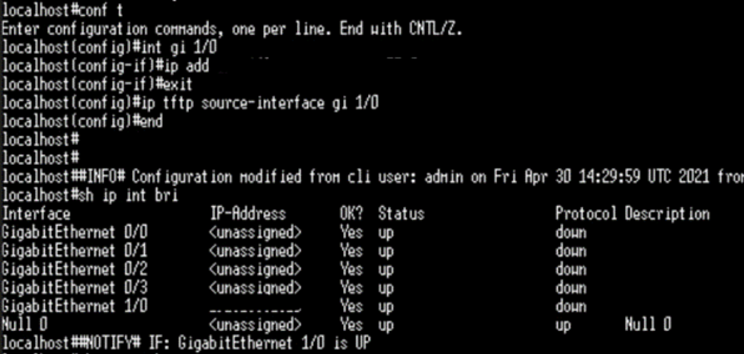
Before this can be done, we need to configure the router to allow data through the TFTP protocol as this is disabled by default for security purposes. We also need to allow data passing on the port to get the new config sent over to the router. Using the correct commands on the router and using the right IP and port will allow me to send the data over.

conf t

conf t - this allows for configuration in the terminal
int gi 1/0 - this goes into gigabit ethernet labelled 1/0
ip add ip and mask - this sets the IP for that port
ip tftp source-interface gi 1/0 - this allows for tftp from port 1/0 as the source
sh ip int bri - shows the interfaces briefly

tftp

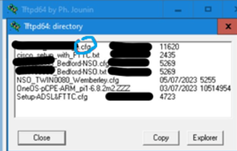
We use a program called Tftpd64 to transfer the config file to the router. We can then send the file over to the router.

update

The update from the TFTP server has not been completed as shown below. We then can reboot the router to ensure the new configuration is on the router.

Once the router has been rebooted, we checked that all the kit can be plugged into the router and we can see that the devices are connected and able to access the internet. We use the sharp command to see if all the devices show up and then ping one of the devices to see if they respond, if they do we then need to check if they can access the internet.

ping

This shows the router can ping googles DNS server showing it can access the internet. Pinging local devices shows that they are connected to the router, and they can also access the internet. We also set the boot config to be the new one as we wouldn’t want to clear the config every time the router reboots itself, it also backs up its config every Sunday evening to make sure that even if the device somehow loses its config, it can be restored. This is also in contact with our Pandora software so if it does go down again, we can be alerted by our monitoring system. We can then work on it appropriately. I learned more about types of lines and how a configuration is installed on a one access router which does use the same commands as Cisco. I would have liked to do an FTTP install too, to learn more about fiber to the property.

Fortinet Firewall VPN Rule

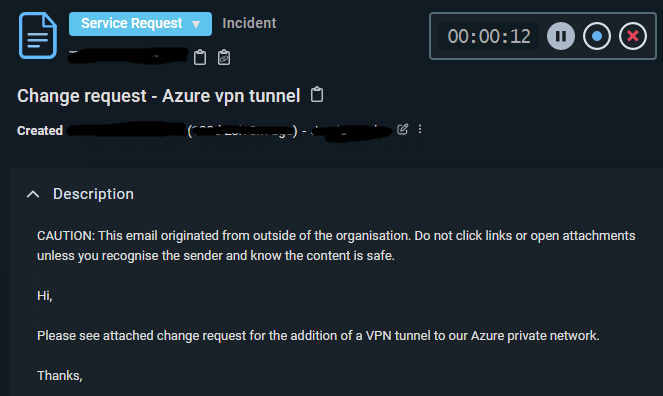
We got this ticket below through for setting up and VPN tunnel to a customer's Azure services. Site to site VPN tunnels typically terminate on a firewall and router on both sides. They both used a preshared key or certificate to connect. Our business uses IPsec, ISAKAMP and IKE. IPsec is a secure network protocol suite that auths and encrypts packets to allow a secure connection between devices. IKE (internet key exchange) is a protocol used to set up a association in the IPsec suite. Our company support both versions 1 and 2 as some legacy devices only support V1 and by default V2 is aggressive and V1 has the option to be aggressive or not. ISAKMP (Internet Security Association and Key Management Protocol) is like IKE but provides the framework for key authentication. There are 2 phases for a connection in IPsec, Phase 1 is The VPN devices negotiate an IKE security policy, authenticate each other, and establish a secure channel. Phase 2: The VPN devices negotiate an IPsec security policy to protect IPsec data.

ticket

First off, the attached change form that was required was wrong as it was also a firewall change request not a VPN template that we require. We first had to get the required form so I sent the following response back to the customer:

form

After that we got the correct document back but the IPs on our side were not filled in and we require a change approver signing to allow the change to happen, this a security method to anyone from changing setting so malicious members cannot change settings. So I then had to go back and request a change approver, I also named the people that are able to approve this request.

change approval

I then got back the form and approval which is shown below:

template

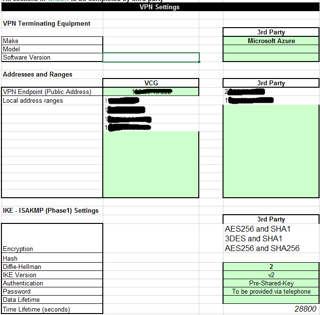
In this document we need the IPs on our side and the IPs on the third parties side, which for this is the Azure service IPs, we also need the setting for phase 1 and 2 of the IKE-ISAKMP. We require the encryption, the hash, The Diffie-Hellman, version of IKE, how its authenticating(preshared key or certificate), password and lifetime in seconds. This information helps us to build the VPN setting or the change in the firewall so it allows access. Once we had the information, we needed I filled it in on our Firewall for the customer, due to use having all the information it makes it easier for us to just put it in and test it.

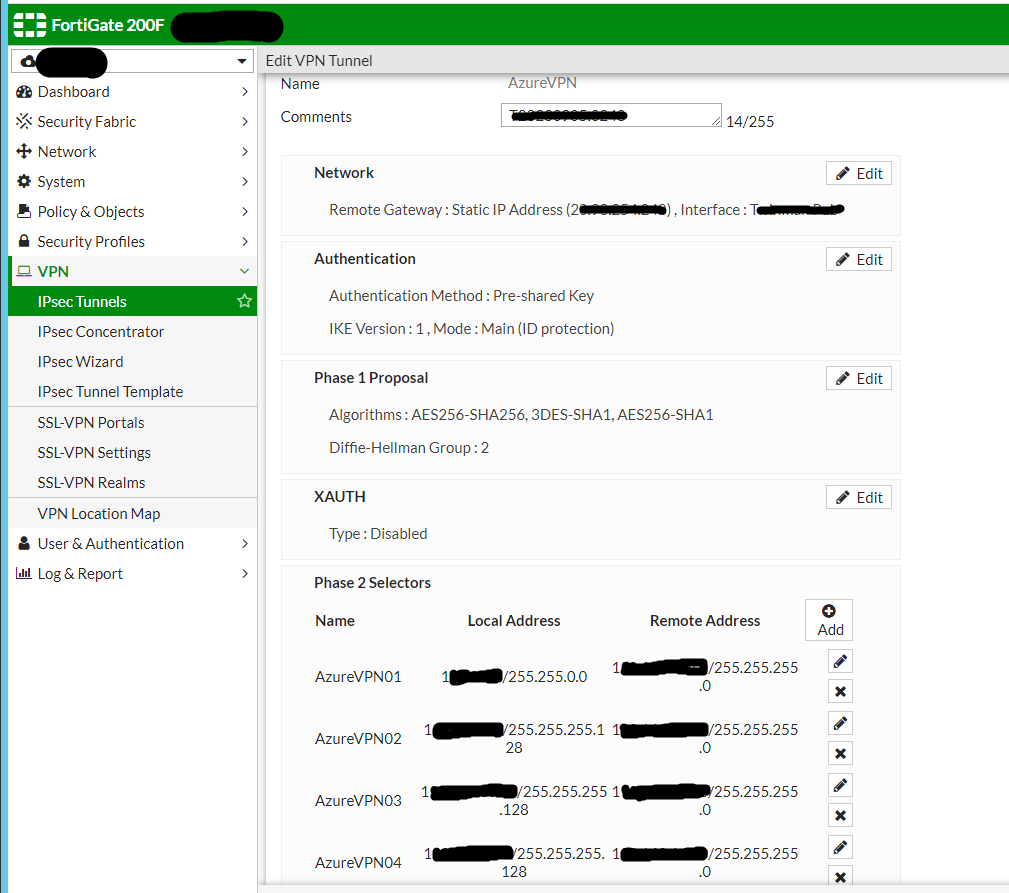
We filled in the name as AzureVPN With the comments of the ticket reference. The gateway IP with it's interface.

IPs provided by customer to the correct remote address which is their Azure service and the local IPs which is our IPs

settings

below is the rule that allows the traffic from the VPN to go to the Azure services and any other data to get redirected to a blackhole. A black Hole in networking is a place where incoming or outgoing traffic is silently discarded while not informing the source that the data didn't reach its intended location. They are essentially invisible without tracking lost packets.

setting

We have a policy set up for traffic going into the Azure tunnel and coming out. This allows for the traffic going in and out of the tunnel to be correctly directed and pushed through.

settings

We use a FortiGate 200F for the firewalls. A firewall is a security device that monitors the incoming and outgoing traffic and can choose whether to block or allow specific traffic based on a set of rules. A firewall can be hardware, software, SaaS or in the cloud. For VPN connections you would most likely have a firewall on each side although this isn't essential. We use a deny all for most sites with exceptions when required as we do have a set of defaults for allowing access and a change request for anything extra. This allows us to heavily control what we allow in and out of the network and see what has been stopped by us and if there is any pattern to it. The specific firewall we use has some extra features that allow us to keep known and zero-day viruses away. It supports Web and DNS security which includes DNS filtering which provides full visibility into DNS traffic while blocking high-risk domains, and protects against DNS tunnelling, DNS infiltration, C2 server ID and Domain Generation Algorithms (DGA). URL filtering leverages a database of 300M+ URLs to identify and block links to malicious sites and payloads. It also uses Zero-day threat prevention which entails Fortinet's AI-based inline malware prevention, our most advanced sandbox service, to analyse and block unknown files in real-time, offering sub second protection against zero-day and sophisticated threats across all NGFWs. The service also has a built-in MITRE ATTACK® matrix to accelerate investigations.

We had an issue with this as the Azure side and ours was set up but we weren't able to get traffic through the VPN by this response to the ticket:

issue

When debugging we noticed that the Phase 1 was being rejected which usually means a mismatch in settings, we knew our side was correct as it get peer reviewed before it gets launched so we can ensure that it is correct so we sent this response back:

resp

But it turns out the user had changed the password without use knowing so we got on a call with them to share the new password securely and ensure that it is the same.

Once we had the correct password on each side got authentication on the logs for phase 2 and connection traffic from each side as shown below:

resp negotiation

There were no longer failures in the logs and the Phase 2 was showing as a success which means we had a connected tunnel and traffic was going through it. The SLA for firewall changes is slightly different at 5 days for completion but if 3rd parties get involved the SLA is paused. This particular task was completed in 4 days and that was due to the comms back and forth between the customer, it slowed us down with the issue that we had which made it still within SLA but slower than usual for this. I learnt a lot about Fortinet firewalls and VPN tunnelling for this which will allow me to use this knowledge in the future. I would like to try this with other types of firewalls as they do vary between manufacturers, and it could be interesting to see how it changes between them. I think the way we do things with a form makes it easier and quicker for us to make the change as we have all the information we need straight away.